AVK MODERN STYLE FIRE HYDRANT, 6" FL INLET, PN 16
A4 bolts, UL/FM, 304/steel stem, 2x2.5" hose, 1x4" pumper, 1.5" pent. op.nut, red EP, drain

Contact
PT AVK Fusion Indonesia
Taman Tekno Blok F1/F - CDE, BSD, Setu, Kec. Serpong. Tangerang Selatan. Banten 15314, Indonesia.
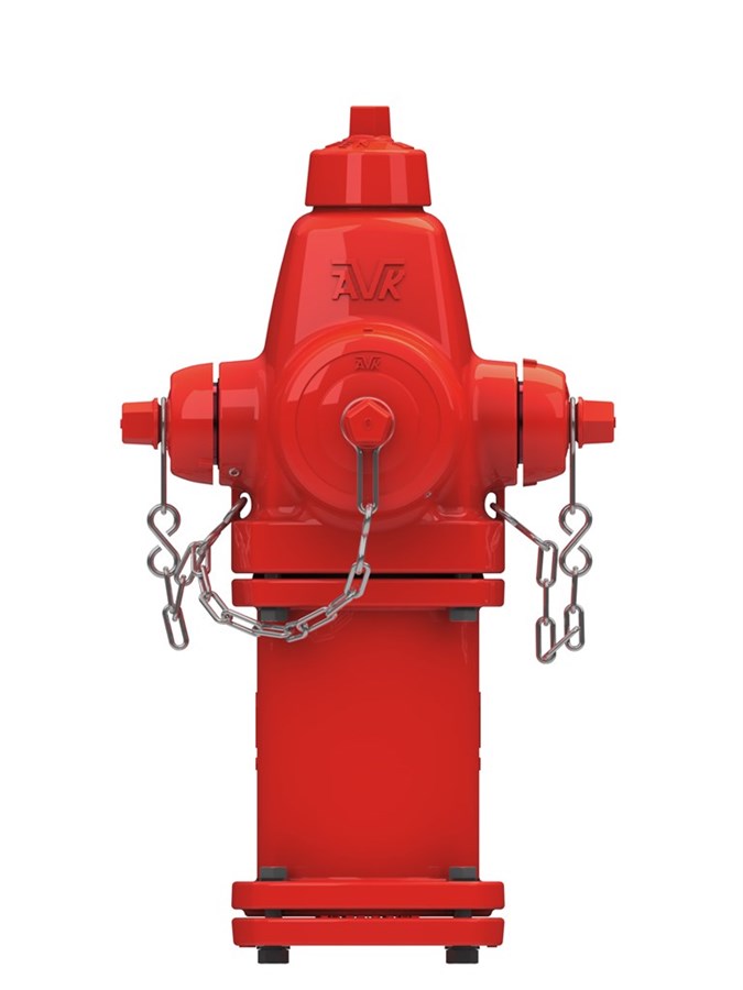
Fire hydrant in modern style for use with firewater to max. 70°C
AVK Series 27 dry barrel hydrants designed to be trouble free and easy to maintain. An automatic drain system frost proofs the barrel by emptying it when the hydrant is closed and a bult-in weak spot makes sure that in case of collision with a vehicle the damage is very limitied and also quick, easy and inexpensive to repair.
To avoid unauthorized use only special tools are able to operate the hydrant.
| Variant 27/24-002 | |
|---|---|
| Connection: | Flanged |
| Material: | Ductile iron |
| DN: | DN150 - DN150 |
| PN: | ANSI CL250 |
| Closing direction: | Open left |
Features
- Fully encapsulated one-piece main valve
- Ductile iron core fully encapsulated in EPDM rubber
- No exposed metal - completely corrosion resistant protected by FBE coating
- UL/ULC listed and FM approved
- High pressure rating to 250 psi
- Ductile iron nozzle section, barrel section, bonnet, and base
- 5.25" valve opening for high flow rating
- Upper section of hydrant repairable under pressure
- 360 degree nozzle section rotation possible
- Traffic proof - if accidentally hit by a vehicle, flange and stem break at a pre-selected weak points that are quick, easy and inexpensive to repair
- 360 degree all bronze drain channel with 2 outlet ports
- Stainless steel stem
- Extensions available in lengths from 6" to 60"
- Extended upper barrels available for deep snow conditions
Downloads
Datasheet
Reference nos. and dimensions:
Scroll for more info
| Reference no. | Text |
DN mm |
H mm |
H1 mm |
H2 mm |
C mm |
Theoretical weight/kg |
|---|---|---|---|---|---|---|---|
| 27-24-O0106-00008-200009 | 4" NST Pump out | 150 | 832 | 540 | 1200 | 200 | 172 |
| 27-24-O0106-00108-200009 | 4 ½” NST pump out | 150 | 810 | 520 | 1200 | 200 | 172 |
| 27-24-O0106-02908-200009 | 4” BS336 pump out | 150 | 832 | 540 | 1200 | 200 | 172 |
| 27-24-O01XX-00008-200009 | 4" NST pump out | 150 | 810 | 520 | Special | 200 | 172 |
| 27-24-O01XX-00108-200009 | 4 1/2" NST pump out | 150 | 810 | 520 | Special | 200 | 172 |
Enquiry
Scroll for more info
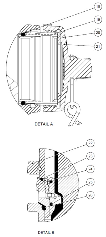
Components
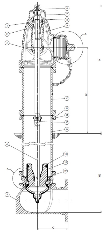
| 1. | Grease nipple | Stainless steel AISI 304 |
| 2. | Nozzle section | Ductile iron A536 65-45-12 |
| 3. | O-ring | NBR rubber |
| 4. | Lower stem rod | Steel |
| 5. | Base | Ductile iron A536 65-45-12 |
| 6. | Weather shield | Cast iron |
| 7. | Stem nut | Bronze |
| 8. | Thrust nut | Bronze |
| 9. | Upper stem rod | Stainless steel AISI 304 |
| 10. | Upper barrel | Ductile iron A536 65-45-12 |
| 11. | Breakable flange | Ductile iron A536 65-45-12 |
| 12. | Lock ring | Stainless steel AISI 304 |
| 13. | Breakable coupling | Stainless steel AISI 431 |
| 14. | Lower barrel | Ductile iron A536 65-45-12 |
| 15. | Main valve disc | Ductile Iron |
| 16. | Disc rubber | EPDM rubber |
| 17. | Valve seat ring | Bronze |
| 18. | O-ring | NBR rubber |
| 19. | Outlet nozzle | Bronze |
| 20. | Cap gasket | NBR rubber |
| 21. | Cap | Cast iron |
| 22. | Stand pipe flange | Ductile iron A536 65-45-12 |
| 23. | Drain Ring | Bronze |
| 24. | Flange | Ductile iron A536 65-45-12 |
| 25. | O-ring | NBR rubber |
| 26. | O-ring | NBR rubber |
Test/Approvals
- Hydraulic test according to AWWA C502, Shell test 500 PSI (2 x Working pressure)
- UL/ULC listed, FM Approved
Standards
- AWWA C502
- Flange drilling to EN1092, PN16